|
The P500 is a member of the Commodore PET-II family of computers. It is a close relative to the Commodore 600 and 700.
While the Commodore 600/700 models were designed as business models with 80 column monochrome video, the P500 was designed as a home computer with 40 column video, featuring the VIC-II chip that was later available in the C64. Because the timing is controlled by the VIC, it is in fact determined by the video standard in use. So the other difference between the 600/700 computers and the P500 is that in the latter, the CPU is clocked with about 1MHz, while the former run with 2MHz.
Feature overview:
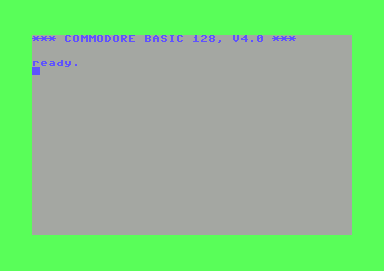
If you have never seen the startup screen of the P500 before, here is a screenshot:
|
If you don't believe that this screenshot is from a real P500, you're right:-) However it is as similar as it can get. The picture was generated by the x64 VICE emulator using a small C program. You may download that program below.
The machine has a CPU produced by CSG (Commodore Semiconductor Group) named 6509, running at 1MHz. The 6509 was based on the 6502 core but was modified to allow access to more than 64K memory using a strange bank switching scheme. Four additional address lines were available, allowing up to 1MB of memory. However, only 64K could be addressed directly. To access more data, there was an additional register located in the zero page at $01. The contents of this register were used as the value for the high four address lines when using the two instructions
lda (zp),yand
sta (zp),y
An additional register located at $00 determined the execution bank, the 64K bank in memory where the CPU fetches instructions from. These registers do not contain zero after a reset (as one could assume) but $0F. Consequently, the system bank (the bank that contains the kernal) is bank 15.
Apart from the strange memory banking, the CPU is a 6502. If you leave the registers at $00 and $01 alone, the CPU may be programmed like a vanilla 6502. However, the additional memory is not accessible in this case.
Video is generated by the VIC-II (the same chip that was later used in the C64). The VIC has access to video and color nibble RAM in the system bank, and to the memory in bank 0. So memory for the high resolution (320*200) graphics mode was in a separate bank.
As the 600/700 machines, the P500 had a SID (Sound Interface Device) chip - the same chip as the C64. While the 600/700 machines had problems reading SID registers, because the SID chip was never designed for a 2MHz clock, reading the SID registers was no problem with the P500. However, the kernal disassembly shows that there were problems accessing the VIC and anything connected to it. While 600/700 machines have a quite complex clock generator, the one in the P500 is a lot simpler, which seemed to cause timing problems in early models. Since the machines never left the prototype stage, all known models have these problems.
The following piece of code shows the - rather complex - ROM routine used when writing values to the VIC. The routine is taken from the -2 ROMs, the latest ROMs known to exist. An additional table is used to mask out bits that are independent of the value written.
|
| Address | Description | |
|---|---|---|
| $E000 - $FFFF | Kernal ROM | |
| $DF00 | TPI 6525 (keyboard) | |
| $DE00 | TPI 6525 (IEEE-488) | |
| $DD00 | UART 6551 | |
| $DC00 | CIA 6526 (IEEE-488, user port) | |
| $DB00 | External port (on coprocessor board) | |
| $DA00 | SID 6581 | |
| $D900 | Low cost disk port | |
| $D800 | VIC-II | |
| $D400 - $D7FF | Color RAM (1KB) | |
| $D000 - $D3FF | Video RAM (1KB) | |
| $C000 - $CFFF | Character ROM (4KB) | |
| $A000 - $BFFF | BASIC ROM high | |
| $8000 - $9FFF | BASIC ROM low | |
| $6000 - $7FFF | Cartridge bank 3 | |
| $4000 - $5FFF | Cartridge bank 2 | |
| $2000 - $3FFF | Cartridge bank 1 | |
| $1000 - $1FFF | Reserved for disk ROM | |
| $0800 - $0FFF | external buffer RAM (2KB) (on coprocessor board) | |
| $0400 - $07FF | RAM, available for user programs | |
| $0002 - $03FF | RAM, used by the system | |
| $0001 | Indirect segment register | |
| $0000 | Execution segment register |
Segments 1 is used for BASIC (so less memory is available than in the 600/700 machines), segments 2-15 are not available in a standard machine. Segment 0 is special because it may be accessed by the VIC. This means that the P500 is capable of displaying several virtual screens of high resolution graphics while having another 64K segment available for the program.
Lines CA and CB of the IEEE-488 TPI determine if the static video RAM and ROMs in the system bank, or segment 0 of the dynamic memory are addressed by the VIC. Bit 6 and 7 of the keyboard TPI, port C are used as additional address bits to select the correct 16K bank for the VIC, similar to the CIA bits in the C64. See the schematics for more information.
Segment 1 is also used for the RS232 and function key buffers.
All of the following pictures are linked to larger versions of the same picture, so just click on the picture for a more detailed view (note: the high resolution pictures are large and may take some time to load).
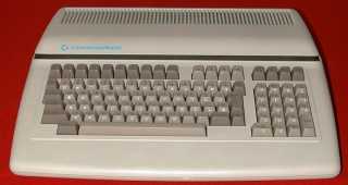
| This is a front view of my P500 machine. As you will notice, it looks identical to the 610, the only difference is the green LED (the 610 has a red LED). There is another difference not visible in this picture: When viewed from the top, one can see the different power supply through the holes on the top. |
|
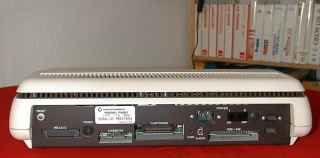
The rear view of the P500. The difference between the case of the P500 and the
610 is that the former has two additional joystick ports on the left side. The
610 has the user port connector at the same place where the P500 had the
joystick ports, but it is not accessible from the outside.
The label with the serial number is also visible in this photo, it reads:
P5001554. As you can see this machine is specified for 117V, 60Hz which is
really unusual here in Europe. The reason for this is simple: It's an U.S.
machine. I have replaced the VIC version to use it with PAL monitors.
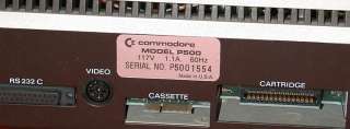
| Here is another view that shows just the label. If you can't read it, click on the photo. |
|
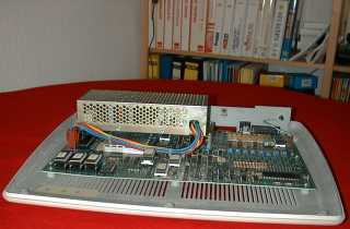
First look with the case open. You can see the power supply, which
is quite different to that of the 610. It's a switching power supply
and stopped working some time after I took these photos. My tries to
get it fixed were unsuccessful, and because I didn't trust it anyway
(it was a very cheap thingie), I replaced it by a power supply of a
610. The metal case below the power supply contains the VIC, the EPROMs on the left side are on sockets as in most 610s. |
|
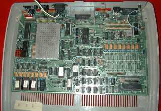
Here is another look with the power supply removed. The 64K dynamic memory
accessible by the VIC is located on the left side near the EPROMs. Segment 1
(accessible to BASIC) is located on the right side. As in the 610 there are
free slots for an additional 128K of RAM.
The keyboard TPI is located in the lower right, the chips in the lower mid
that look like ROMs are the character ROM (same part number as in the C64) and
two PLAs. The large chips below the module slot are the CPU and the SID.
Another picture with the video shielding removed. As stated above, I've replaced the VIC by a PAL version from a C64.
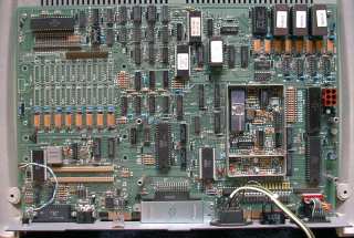
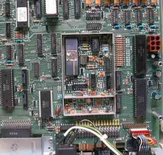
| A view on the main CPU. To the right of the 6509 CPU, the 6581 SID (Sound Interface Device - this was the same chip as in the C64). The chip on the left is the 6551 UART and the crystal needed to generate the RS232 clock. The two 60 pin connectors between the CPU and the UART are processor extension ports (called "system bus connectors" in the schematics) used for the coprocessor cards. However, since there is no coprocessor support in the ROM, I would assume that the P500 was never tested with one of these cards. |
|
|
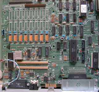
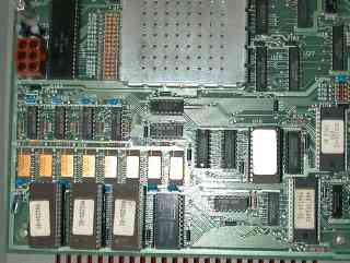
A closeup of the EPROMs and PLAs. From left to right: KERNAL, BASIC
low and BASIC high eproms. As you can see, the machine contains the
-02 ROM versions. They differ greatly from the -01 versions but do
still have lots of errors. I've never seen a newer version of these
ROMs. If you know about a later version, please
drop me a mail. The chips on the left of the video shielding are the 6525 TPI driving the IEEE-488 port and the CIA used for the joystick port (among other stuff). The joystick ports are visible in the upper left. |
| Last photo: A view into the shielding that contains the video signal generation. The IEEE-488 port is also visible between the module and joystick ports. |
|
There is not much information available on the net, so I've tried to gather available materials and links:
Materials:
P500 startup screen generator in C P500 kernal and BASIC ROMs (the -01 ROMs were donated by Michael Sachse, <cbmcomputer@gmx.de>) Schematics for the P500 A ROM disassembly of the -02 ROMs generated by da65 using this info file
Links:
"P500 aka CBM 510" by Michael Sachse Steve Grays B series page Bo Zimmermanns P500 The secret weapons of Commodore
![]()